

 |
|


|
|
I'm Online Chat Now
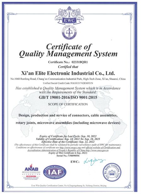
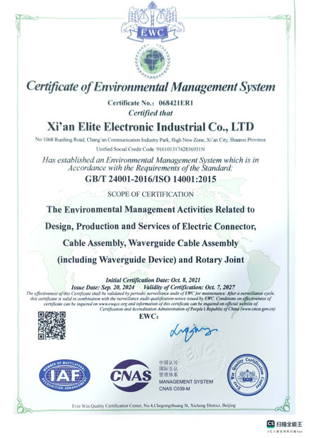
Certification
Company News
What Influences the VSWR Performance of RF Coaxial Connectors

1. Inner and Outer Conductor Diameter Tolerance
Standard 50Ω connectors adopt fixed matched dimensions for inner and outer conductors. Even tiny machining deviations will alter characteristic impedance and cause impedance discontinuities, resulting in degraded VSWR. Sensitivity rises sharply with frequency; deviations of several thousandths of an inch will trigger obvious VSWR spikes at frequencies above 18 GHz.
1.1 Center Conductor Concentricity / Alignment Precision
Eccentricity or offset of inner conductors after male-female mating disrupts electromagnetic field distribution and creates impedance discontinuities, drastically worsening VSWR at high frequencies.
1.2 Interface Geometry of Connection Port
Irregular machining of flanges, steps, transition sections and threaded contact surfaces leads to abrupt changes in signal transmission paths and induces signal reflection.
1.3 Mechanical Machining Tolerances
Out-of-tolerance dimensions of overall connector length, dielectric steps and transition steps generate resonant points, causing sharp VSWR surges at specific frequency bands.
2. Relevant Parameters of Dielectric Materials
2.1 Dielectric Constant
Batch-to-batch fluctuations in the dielectric constant of materials such as PTFE directly change unit capacitance and break the standard 50Ω impedance matching.
2.2 Uniformity of Dielectric Thickness
Uneven dielectric thickness or deformation caused by assembly compression leads to fluctuating local impedance and signal reflection.
2.3 Dielectric Assembly Gaps, Cracks and Material Shortages
Misaligned dielectric layers or air gaps at the male-female mating interface create large differences between the dielectric constant of air and solid dielectric, significantly deteriorating VSWR.
3. Connector Structural Length and Resonance
Improper overall connector length or internal transition section length induces resonance within the operating frequency band and produces VSWR peaks. Higher frequency bands allow far less margin for length design errors.
4. Conductor Surface Finish and Plating Process
4.1 Surface Roughness
Excessive surface roughness of conductor contact surfaces distorts local electromagnetic fields, increases signal reflection, and simultaneously elevates insertion loss and VSWR, especially at high frequencies.
4.2 Electroplating Quality
Thin, uneven, oxidized, pitted or peeled gold plating creates unstable contact resistance and triggers RF reflection. VSWR continues to degrade as oxidation accumulates during long-term service.
4.3 Burrs and Scratches on Contact Surfaces
Tiny surface irregularities disrupt RF electric fields, with particularly severe impacts at millimeter wave frequencies and above 18 GHz.
5. Assembly and Mating Performance
5.1 Male-Female Mating Clearance
Excessively loose or tight thread fit, or oversized gaps between inner conductor pins cause unstable contact and intermittent impedance discontinuities.
5.2 Non-Standard Torque for Locking
Excessive torque crushes and deforms outer conductors, while insufficient torque results in poor contact; both scenarios damage impedance matching structures.
5.3 Cascaded Multi-Connector Adapters
Multiple consecutive adapters create multiple impedance discontinuities with superimposed reflections, worsening overall VSWR performance.
6. Service Operating Environment
6.1 Temperature Variation
High and low temperatures trigger thermal expansion and contraction of metals and dielectrics, leading to dimensional deformation, impedance drift and temperature-dependent VSWR shifting.
6.2 Vibration and Wear from Mating Cycles
Repeated plugging and unplugging abrade plating layers; long-term vibration causes inner conductor offset and loose threads, gradually degrading VSWR over time.
6.3 Humidity and Corrosion
Moisture corrodes conductor plating and forms oxide layers, increasing reflection loss.
7. Derivative Impacts for Cable Assembly Applications
Poor crimping or soldering between connectors and RF cables: misaligned crimping of inner/outer cable conductors, cold solder joints or broken shielding layers create abrupt impedance changes at the cable-connector transition, pushing the overall assembly’s VSWR out of specification.
Pub Time : 2026-08-12 10:15:12
>> News list
Contact Details
Xi'an Elite Electronics Co., Ltd.
Contact Person: Ms. Elite
Tel: +8613609167652
Send your inquiry directly to us